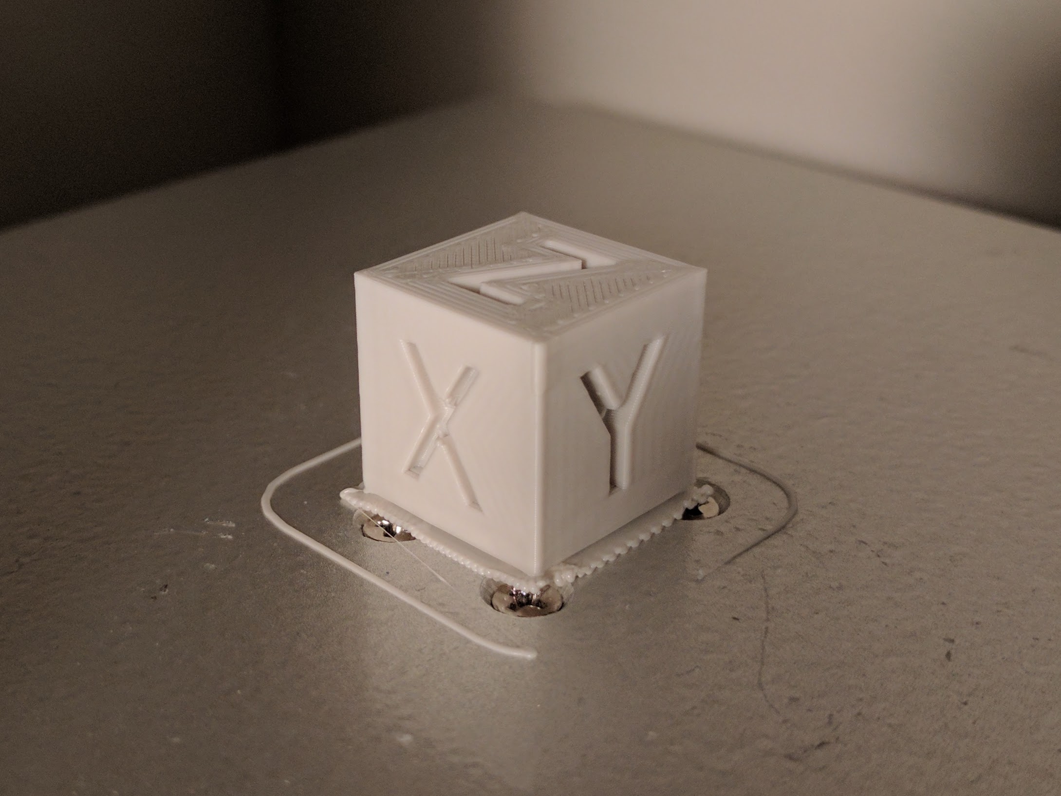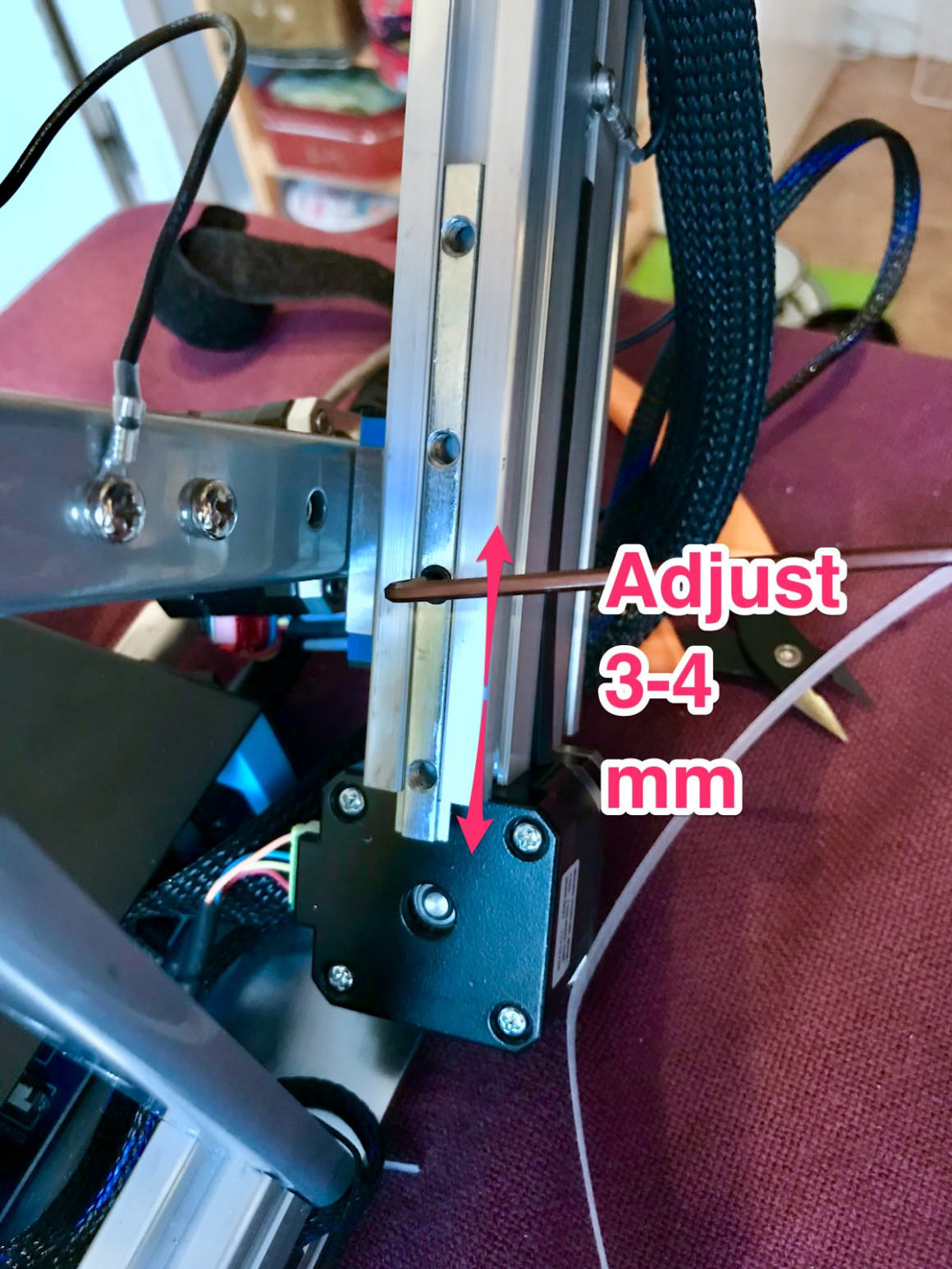

Perhaps the info below will help someone in the future:Ī) I used the start and end code from chrisevich ( #11) which worked nicely for me.ī) the z-axis calibration code posted by cmeyer never worked for me. I just wanted to thank everyone who contributed to this thread - it helped me tremendously when setting up my Cetus3D MkII with Cura. G1 X50 E360 F300 extrude a 5cm purge line G1 X2 Y178 F5000 move to back right corner M206 X-180 offset X axis so the coordinates are 0.180, normally they are -180.0 Do the paper test and use a gcode file something like this:p.p1 the nozzle offset may be different than in Cetus Studio. All you need to buy is the heated build plate from the Tiertime website.- make sure your nozzle offset is correct in the starting g-code This one is only compatible with the mk1 and mk2. If you just got the new mk3 then I think they have a new heated build plate that can reach higher temperatures but I was having trouble with the Tiertime website so I couldn't find it. I've been using this magnetic surface on my Cetus mk2. I cut them to be the correct size and then make holes in the adhesive magnetic surface (NOT the top magnetic surface that you will actually print on) where the screws attach the build plate to the linear rail. This way I can remove the magnetic top surface and tighten the screws incase they come loose without having to try and remove the adhesive magnetic layer. If that doesn't make sense I can post photos later to better explain. Usually the type of filament and the shape of the print will effect the difficulty of removing rafts and supports.įor example, when I use filament from Cetus (Tiertime) I've had very little trouble removing rafts. Although sometimes I still needed to use some tools to help out. When I use Hatchbox filament, removing everything is much more difficult. Except for when I used Hatchbox PLA Wood filament. Tools are usually used to at least clean up leftover pieces of plastic or to initiate the rafts removal. The complexity of the print has also been a factor in how difficult removal of the raft is.Īre you using the heated build plate or the non heated one that comes standard with the printer? I switched to the heated version ASAP and stopped using rafts for most of my Cetus prints. This also requires you to dile in the nozzle height and leveling in the bed. I installed a removable magnetic build surface to my heated build plate and now almost never use rafts and removal of the prints is very easy. What settings make the raft easy to peel? Is that on UP Studio or different software? Rarely have to use glue with this setup as well. Keep in mind that I'm still very much new to printing myself.Ever wanted to see printer step or micro step errors then this is the test for you. Honestly this test has way more resolution than a printer can handle. In a perfect world the test would be used to calibrate out position errors and improve printer accuracy. :added May 2020 stl file to print in vase mode, no corners so you can print it fast. I converted my Cetus electronics to Duet2 WIFI electronics new pic is the Duet2 printing the new stl file. Layers are 0.15mm thick which is the vertical bands spacing for calibrating horizontal measurements. My tuned up cetus mk2 with IKO linear rails printed the walls in the picture. The edge of each layer forms a cylinder which also doubles as a lens. When the two lens interact your mind sees a pattern. The interference band down the middle has the smallest horizontal errors because the horizontal stepper position is almost identical and position errors between the two walls track each other.

Move away from the center and the horizontal position errors become more independent and cause the bands to wiggle. Z stepper height errors change the vertical width of the center dark band. Moisture in PLA creates steam and this effects the lens shape so dry PLA is best.

You can see the timing belt tooth spacing, micro stepper errors, and even the extruder filament feed teeth as patterns in the wall print. Any pattern you see that is not vertical, horizontal or parallel to a close by edge is an extruder or ball problem in a bearing. Use translucent PLA and print two walls one at a time and parallel to one horizontal axis. Choose slicer settings to make a hollow center and cut the front and back apart. Place two front walls contacting each other (no flipping) with a few degree angle between the printed layers.


 0 kommentar(er)
